Electronics Basics
What to know before wiring a device.
Digital Input and Output
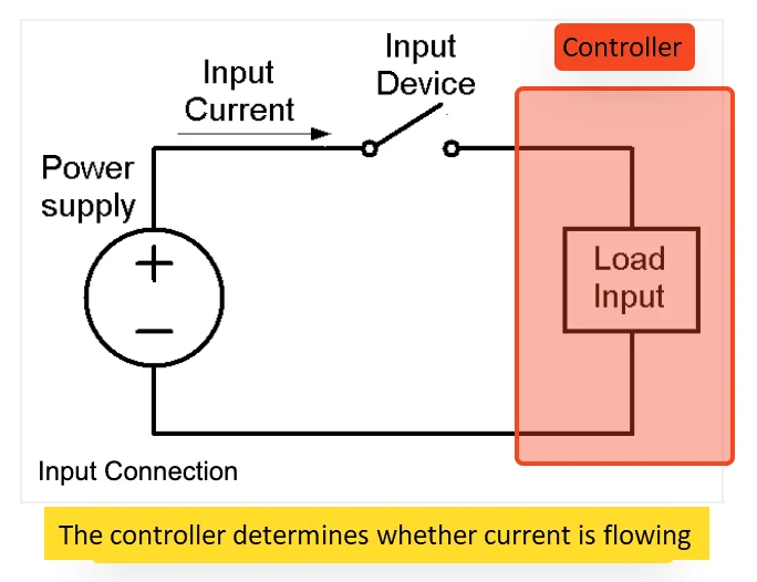
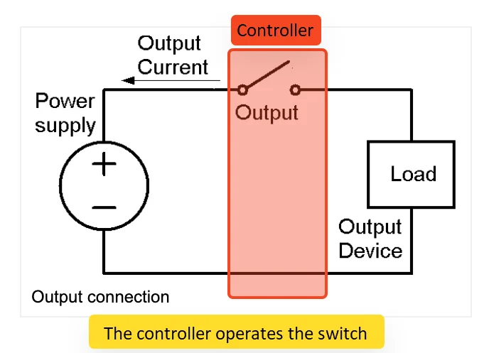
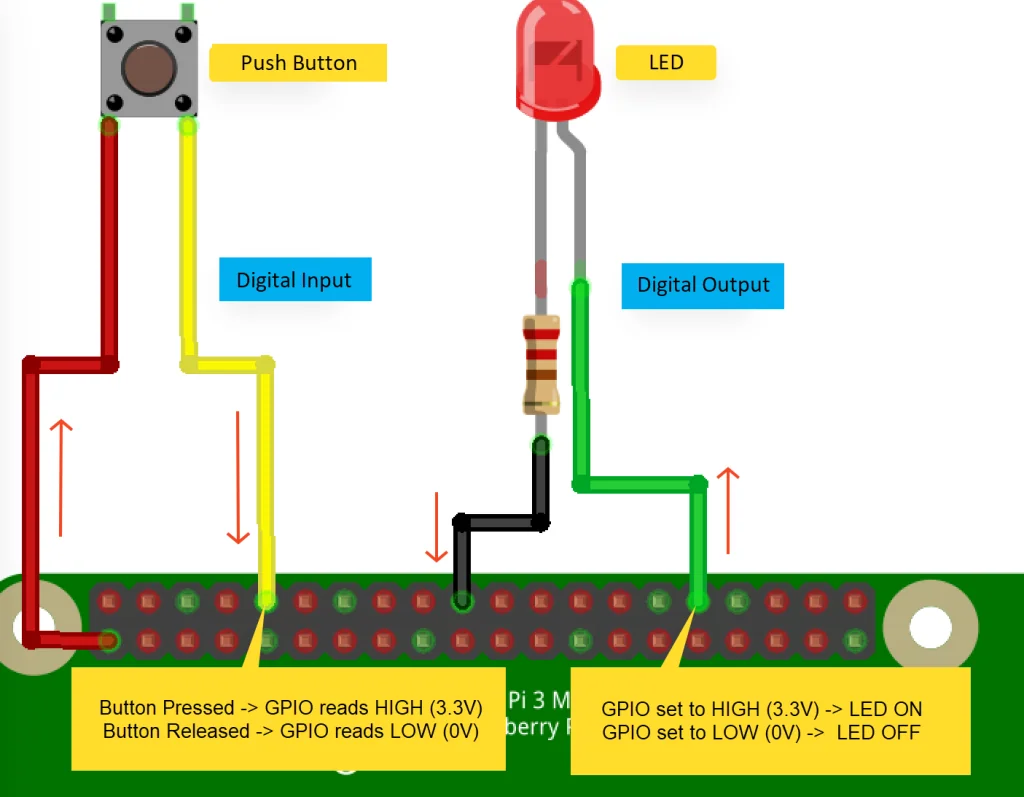
In a digital circuit, current flows when the switch closes and stops when it opens. The closed state is HIGH and the open state is LOW. A digital input is the controller sensing that opening and closing on an external switch; a digital output is the controller driving it.
Analog Signals and ADCs
Values that vary continuously, such as light level or sound volume, are analog signals. The controller only handles digital signals, so reading an analog signal needs an ADC (Analog-Digital Converter) and producing one needs a DAC. The Raspberry Pi has no analog input pins, so register an ADC device such as the ADS1115 as an I/O device.
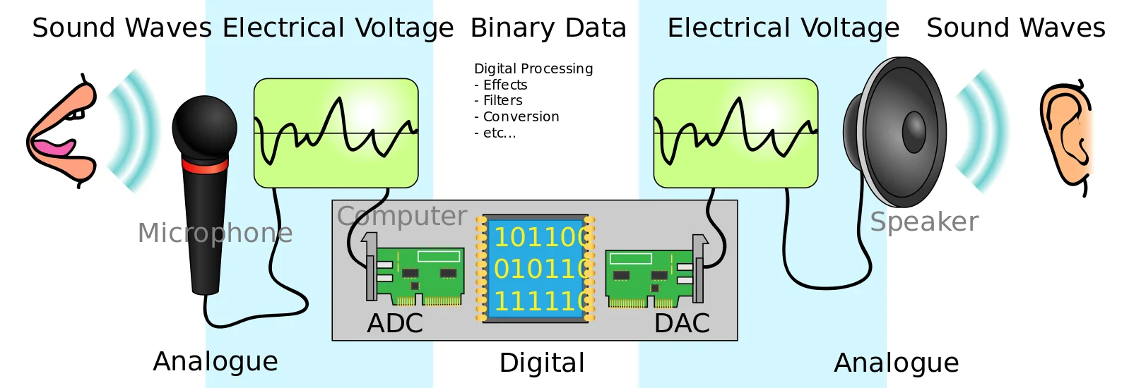
A digital signal has only two states: current flowing (ON, 1, true) or not flowing (OFF, 0, false). A light switch and a computer's data processing are digital; light level, sound volume, and wind strength are analog. Sound entering a microphone (an analog voltage), for example, is converted to digital data by an ADC, processed, then converted back to an analog voltage by a DAC and played by a speaker. For the units of digital data, see Bits and Bytes.
Calculating an LED Resistor
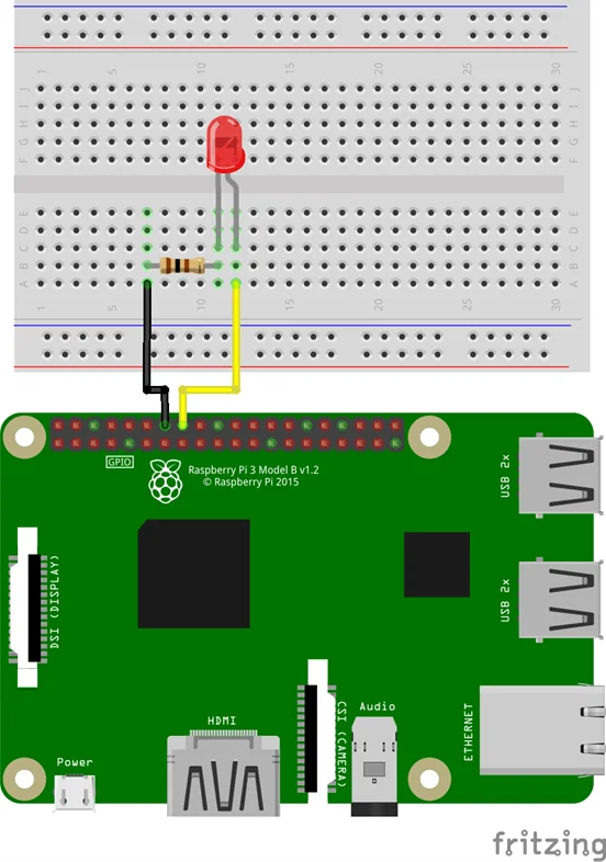
When the supply voltage is higher than the LED's forward voltage, a resistor must limit the current. Without one, current far above the rating flows and the LED is damaged. Ohm's law gives the value.
R = (supply voltage - LED forward voltage) / current
For a red LED with a 2V forward voltage on a 3.3V GPIO, allowing for the Raspberry Pi's per-pin output limit of about 8mA and targeting 5mA, the result is about 260Ω. The commonly available 220Ω gives about 5.9mA, comfortably within range. The resistor may go on either leg of the LED.
An LED's forward voltage and forward current are listed in its datasheet. For a red LED rated at 2V and 20mA, Ohm's law (V = I × R) gives (3.3V − 2V) / 0.02A = 65Ω, but that exceeds the Raspberry Pi's GPIO output limits (about 8mA per pin, 50mA in total), so the value is recalculated at 5mA as above. With less than the rated 20mA the LED is somewhat dimmer, but bright enough for normal use.
LED forward voltage by color and recommended resistors
Typical values to refer to when no datasheet is available. Actual values vary by product.
| Color | Forward voltage | Typical current |
|---|---|---|
| Red | 1.8–2.3V | 20mA |
| Orange | 2.0–2.3V | 30mA |
| Yellow | 2.0–2.8V | 20mA |
| Green (yellow-green) | 1.8–2.3V | 20mA |
| Green (true green) | 3.0–3.6V | 20mA |
| Blue | 3.4–3.8V | 20mA |
| Pink | 3.4–3.8V | 20mA |
| White | 3.4–4.0V | 20mA |
Approximate resistor values for a Raspberry Pi (3.3V), calculated as above:
| Color | Resistor |
|---|---|
| Red | 220Ω |
| Yellow | 180Ω |
| Green | 220Ω |
| White | 100Ω |
Pull-up and Pull-down Resistors
With a push button released, an input pin connected to neither the supply nor ground is neither HIGH nor LOW but floating. In that state, noise or static can flip the value arbitrarily and it cannot be controlled. A pull-up resistor pins the released state to HIGH and a pull-down resistor pins it to LOW, removing the problem.
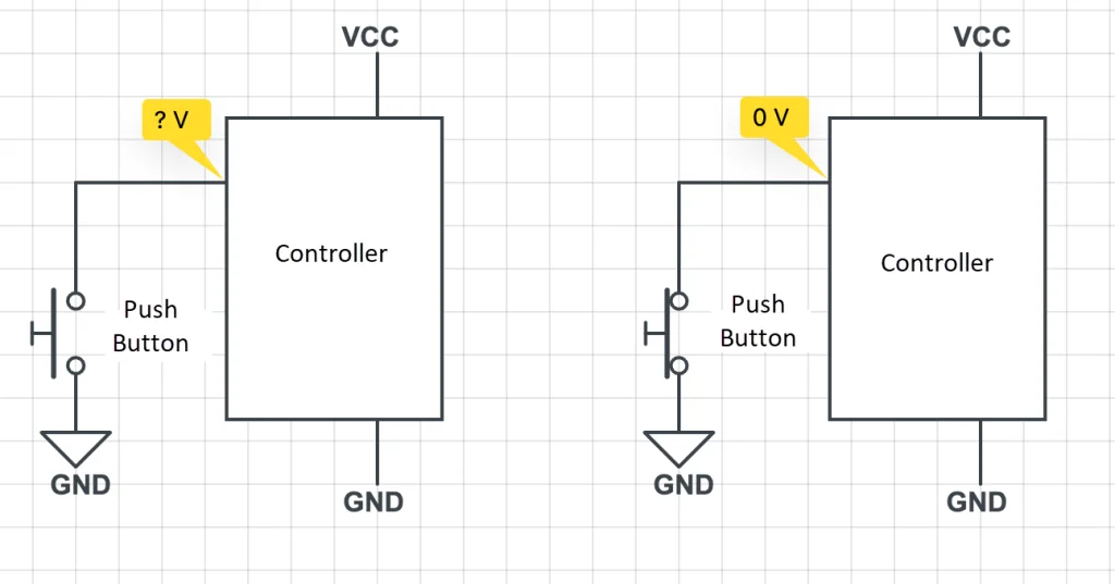
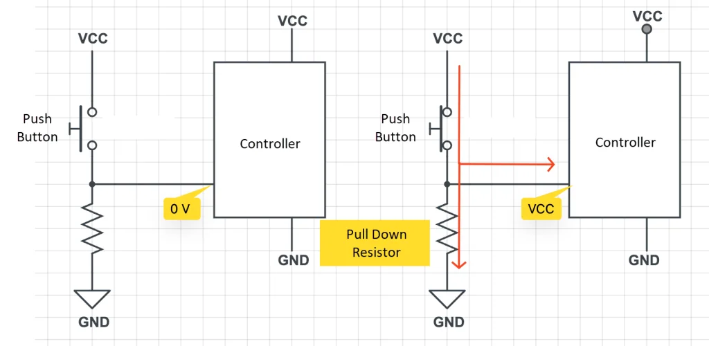
An input pin reads HIGH when connected to the supply (VCC) and LOW when connected to GND. If a push button is wired only to GND, as on the left below, the input pin is tied to GND and reads 0V (LOW) while pressed, but floats at an unknown voltage while released.
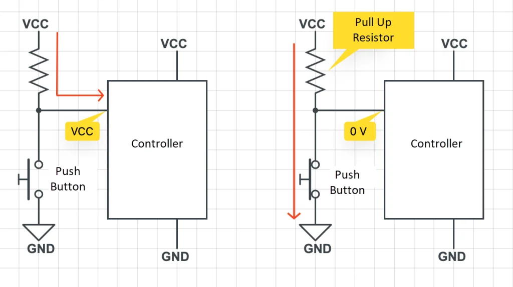
With a pull-up resistor between the input pin and VCC, current flows into the input pin while the button is released, giving HIGH, and flows to GND while it is pressed, giving LOW.
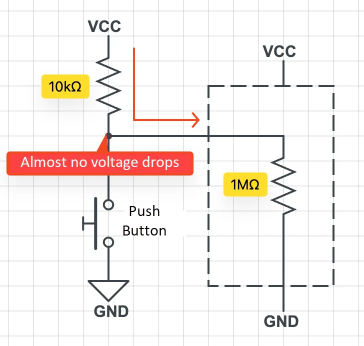
The input pin's impedance (100kΩ to 1MΩ) is far larger than the pull-up resistor, so the two act as resistors in series and almost no voltage drops across the pull-up. The input pin therefore sees a voltage close to VCC.
A pull-down resistor goes between the input pin and GND. It pins the released state to LOW and prevents excessive current (a short circuit) to GND while the button is pressed.
Converting Between 3.3V and 5V
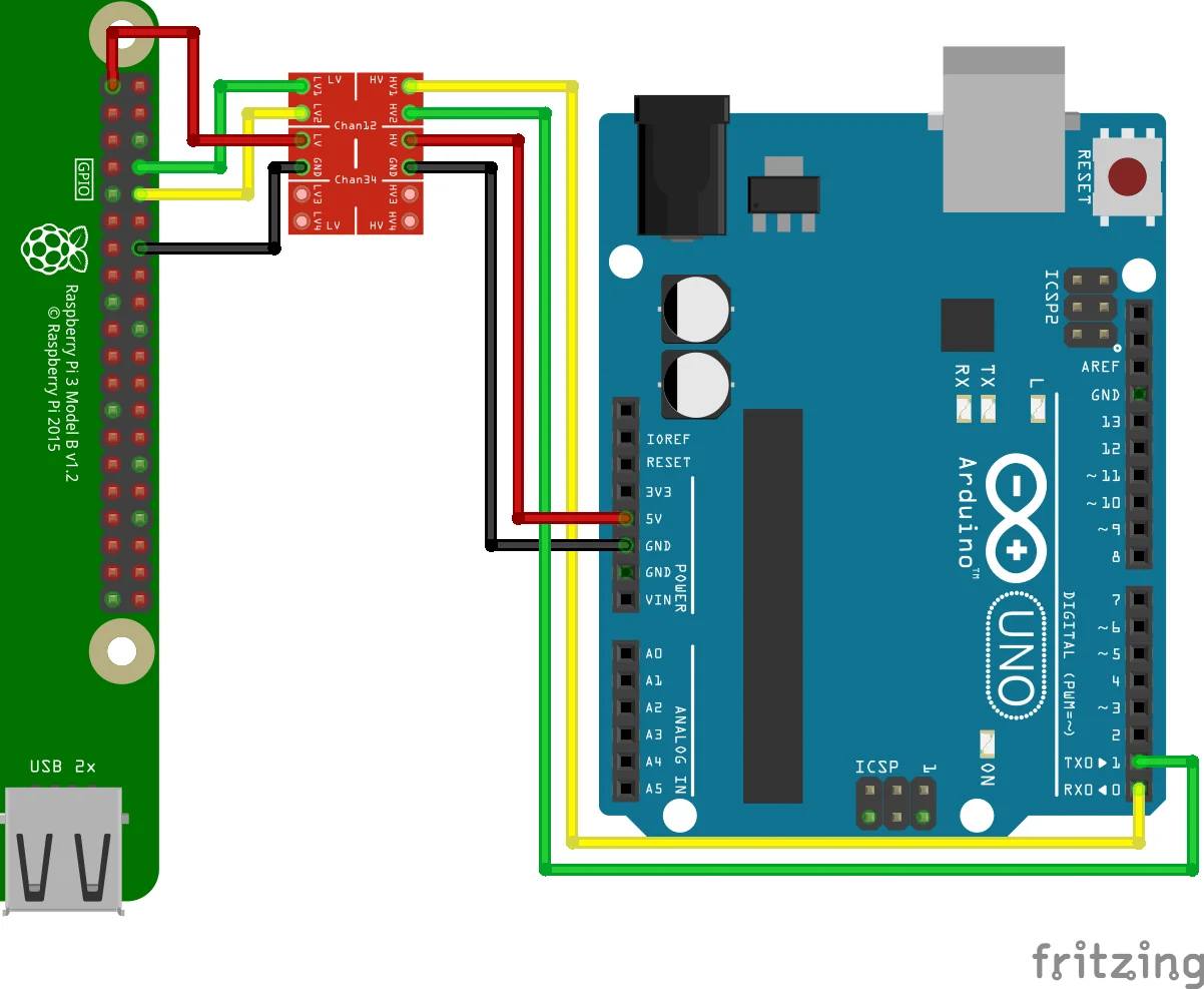
Raspberry Pi GPIO runs at 3.3V. Connecting a 5V-only sensor, or a 5V board such as an Arduino Uno, requires level conversion; connecting 5V without it damages the board.
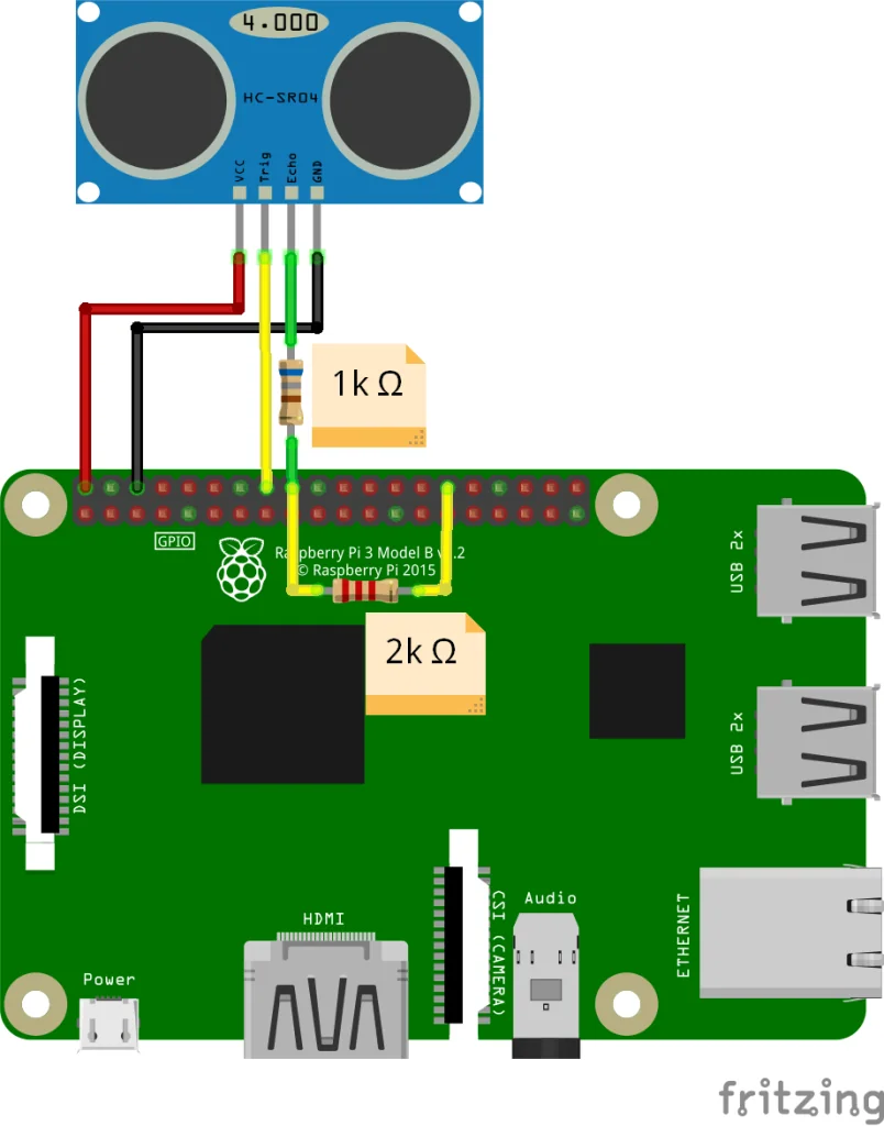
- Voltage divider: Two resistors lower the voltage. To bring 5V down to 3.3V, for example, R1 of 1kΩ with R2 of 2kΩ produces about 3.3V. Use this for incoming 5V signals such as the echo pin of an HC-SR04 ultrasonic sensor.
- Logic level converter: A module supporting bidirectional conversion across several channels. Use it for two-way signals such as communication lines, wiring the higher voltage to HV and the lower to LV.
Raspberry Pi, Jetson Nano, and the Arduino Due, Zero, and Nano 33 IoT are 3.3V devices; the Arduino Uno, Nano, Mega, and Leonardo are 5V devices. Level conversion is needed in these cases:
- Connecting a sensor or module with a 3.3V output to a 5V device
- Connecting a sensor or module with a 5V output to a 3.3V device
- Communication between a 3.3V device and a 5V device
The output voltage of a divider is given below, with R1 on the input side and R2 on the GND side.
Vout = R2 / (R1 + R2) × Vin
Logic level converters come in unidirectional types, which convert one way only, and bidirectional types, which convert both ways. Use a bidirectional type for links with transmit and receive lines such as UART.
Serial Communication Standards
A UART (Universal Asynchronous Receiver/Transmitter) is hardware that sends and receives data serially; "serial communication" usually means communication over a UART. It communicates one-to-one over two pins, TX (transmit) and RX (receive), converting the CPU's parallel data into serial data for sending and received serial data back into parallel data.
UART communication is asynchronous, so both devices must use the same baud rate, number of data bits, parity type, and number of stop bits. These are the communication settings of Modbus RTU and User Defined Communication (serial).
| Standard | Characteristics |
|---|---|
| TTL UART | Wires the board's UART pins directly. Suited to short distances and one-to-one links. |
| RS-232 | The standard PC serial interface. One-to-one, and its voltage levels differ from TTL, so a converter is needed. |
| RS-422 | Differential signaling for longer distances, used for one-to-many in one direction. |
| RS-485 | Differential signaling that tolerates long runs and puts several devices on one pair. Widely used for industrial Modbus RTU. |
TTL Levels
TTL (Transistor-Transistor Logic) levels are one way of defining the voltage ranges read as HIGH (ON, 1) and LOW (OFF, 0). The 5V TTL levels are:
| State | Input | Output |
|---|---|---|
| HIGH (ON, 1) | 2–5V | 2.7–5V |
| LOW (OFF, 0) | 0–0.8V | 0–0.4V |
UARTs use TTL levels. With low voltage levels and a small noise margin (the gap between the input and output thresholds), they are sensitive to noise and limited in distance, so they are mainly used inside a device or over short distances.
RS-232, RS-422, RS-485
These standards make up for the UART's weaknesses, tolerating noise and reaching further. They cover hardware and voltage levels; the communication protocol is still UART.
| Item | RS-232 | RS-422 | RS-485 |
|---|---|---|---|
| Signaling | Single-ended | Differential | Differential |
| Network | 1:1 | 1:N (multi-drop) | 1:N (multi-drop) |
| Wiring | 3 wires: TX, RX, GND, with TX and RX crossed between the two ends | 4 wires: TX+, TX-, RX+, RX- | 2-wire or 4-wire |
| Maximum distance | About 15m | About 1.2km | About 1.2km |
| Maximum speed | 20kb/s | 10Mb/s | 10Mb/s |
| Maximum output voltage | ±25V | -0.25V to +6V | -7V to +12V |
| Maximum input voltage | ±15V | -7V to +7V | -7V to +12V |
| Devices | 2 | 1 master, up to 10 slaves | Up to 32; any device can be master |
- RS-232: Uses ±12V levels to reach further.
- RS-422: Differential signaling, where the same noise on the + and - lines cancels out, makes it noise tolerant. With the master fixed to a single device, it is not a true multi-drop setup.
- RS-485: Similar to RS-422, but any device on the network can be master or slave. On long runs, termination resistors are sometimes fitted at both ends of the line to reduce noise.
Motors and Relays
DC motors are controlled by voltage for speed, servo motors by a PWM signal for angle, and stepper motors by pulse count for rotation. All three are supported as I/O devices (Part 7).
- DC motor: High starting torque, with output torque proportional to input current. Reversing the polarity reverses the rotation. A motor driver allows forward and reverse rotation and speed control with a PWM signal.
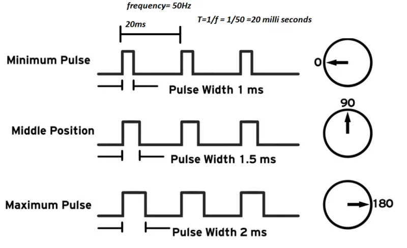
- Servo motor: Commonly called an RC servo; it turns to and holds an angle between 0 and 180 degrees according to the pulse width of a PWM signal. It is not suited to continuous rotation or speed control, and differs from industrial servo motors.
- Stepper motor: Turns one step per input pulse. Its high resolution suits precise position and speed control, as in 3D printers and production equipment. It is driven through a stepper driver such as the A4988, which must receive exactly as many pulses as steps, at accurate timing.
A relay is an automatic switch operated by an electrical signal, also called an electromagnetic relay. Instead of pressing a switch by hand, a weak electrical signal opens and closes its contacts. Controller outputs are limited (DC 5V at up to 40mA on an Arduino, DC 3.3V at about 8mA per pin on a Raspberry Pi), so large loads are switched through a relay. Relays come in two kinds:
- Electromechanical relay: A small current through the coil closes the contacts magnetically; when the current stops, a spring opens them.
- Solid state relay (SSR): Switches with semiconductors and no moving parts. It switches fast and lasts long.
Multithreading and Execution Interval
A thread is a unit of work that runs independently inside a program, and multithreading is one program handling several tasks at once through several threads. Each Grablo logic also runs in its own thread.
One CPU core runs only one task at a time, so when there are more threads than cores the operating system allocates the CPU to them in turn. This is called scheduling, and switching the running task is called context switching. As a result, each thread's execution time varies with CPU performance and load; a logic set to run every 100 milliseconds, for example, may actually run at intervals longer than 100 milliseconds. Control that needs more precise timing requires a real-time operating system (RTOS). For the execution interval setting, see Part 4.