Hardware Pinouts and Interfaces
Raspberry Pi
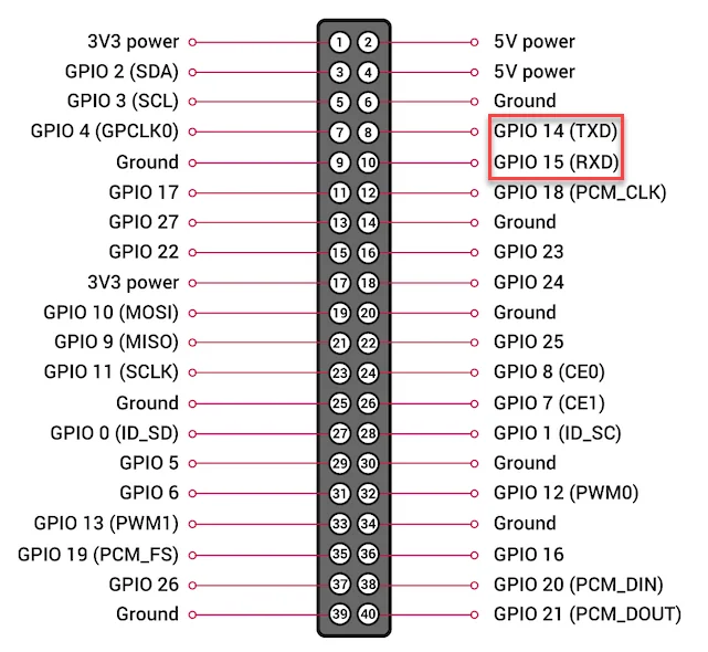
Every current model provides a 40-pin header, and each pin has the same function across models. Pins can be numbered by connector position (Physical/Board) or by CPU channel (GPIO/BCM); Grablo uses GPIO/BCM.
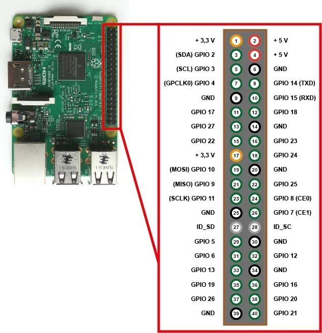
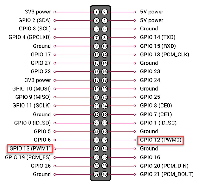
Full 40-pin header map (pin number ↔ GPIO number)
| Name | Pin | Pin | Name |
|---|---|---|---|
| 3.3V | 1 | 2 | 5V |
| GPIO 2 (SDA) | 3 | 4 | 5V |
| GPIO 3 (SCL) | 5 | 6 | GND |
| GPIO 4 (GPCLK0, default 1-Wire) | 7 | 8 | GPIO 14 (TXD) |
| GND | 9 | 10 | GPIO 15 (RXD) |
| GPIO 17 | 11 | 12 | GPIO 18 (PCM_CLK) |
| GPIO 27 | 13 | 14 | GND |
| GPIO 22 | 15 | 16 | GPIO 23 |
| 3.3V | 17 | 18 | GPIO 24 |
| GPIO 10 (MOSI) | 19 | 20 | GND |
| GPIO 9 (MISO) | 21 | 22 | GPIO 25 |
| GPIO 11 (SCLK) | 23 | 24 | GPIO 8 (CE0) |
| GND | 25 | 26 | GPIO 7 (CE1) |
| GPIO 0 (ID_SD) | 27 | 28 | GPIO 1 (ID_SC) |
| GPIO 5 | 29 | 30 | GND |
| GPIO 6 | 31 | 32 | GPIO 12 (PWM0) |
| GPIO 13 (PWM1) | 33 | 34 | GND |
| GPIO 19 (PCM_FS) | 35 | 36 | GPIO 16 |
| GPIO 26 | 37 | 38 | GPIO 20 (PCM_DIN) |
| GND | 39 | 40 | GPIO 21 (PCM_DOUT) |
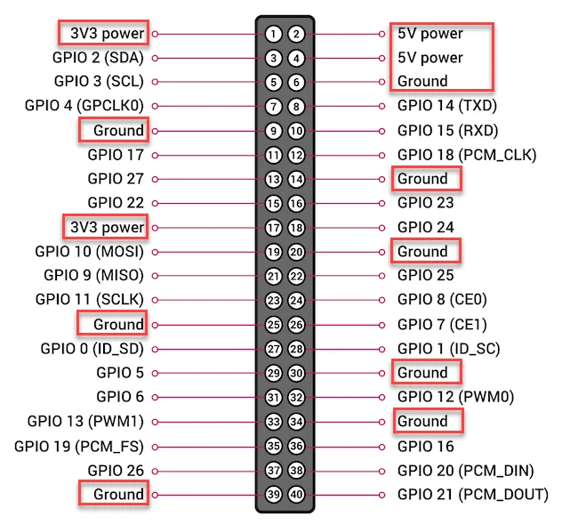
The pins that supply power to external devices are 3.3V on pins 1 and 17 and 5V on pins 2 and 4; GND is on pins 6, 9, 14, 20, 25, 30, 34, and 39. A commercially available GPIO extension board makes connecting to a breadboard and similar more convenient. Details on each pin are available at pinout.xyz.
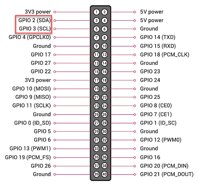
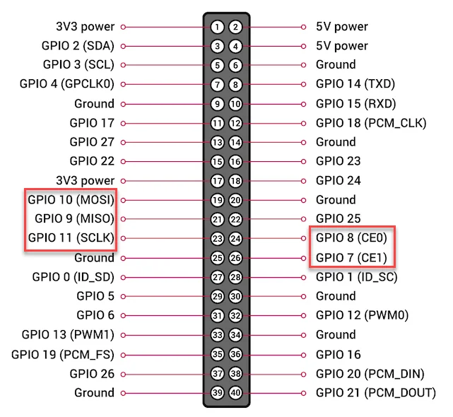
Pin locations by function
| Function | Pins | Notes |
|---|---|---|
| I2C | GPIO 2 (SDA), 3 (SCL) | Also usable as general digital I/O. |
| SPI | GPIO 7, 8, 9, 10, 11 | Also usable as general digital I/O. |
| UART | GPIO 14 (TX), 15 (RX) | The primary UART. Also usable as general digital I/O. |
| Hardware PWM | GPIO 12, 13 | Also usable as general digital I/O. |
| 1-Wire | GPIO 4 | The default, changeable with the procedure below. |
Apart from the power pins, every GPIO pin runs at 3.3V. The current limits are 0.5mA per input and about 8mA per output, with the sum across all output pins staying under 50mA. On the power pins, the 3.3V rail supplies about 800mA and the 5V rail about 2.5A minus what the board itself (camera, USB, and so on) and the 3.3V rail draw. The Raspberry Pi has no analog input pins, so reading an analog signal requires an ADC such as the ADS1115.
Jetson Nano
On the Jetson Nano, pin numbers and GPIO numbers are different schemes. Enter the GPIO number in Grablo.
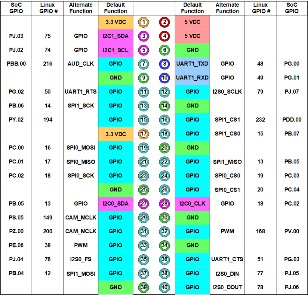
The power pins are 3.3V on pins 1 and 17 and 5V on pins 2 and 4; GND is on pins 6, 9, 14, 20, 25, 30, 34, and 39. The pins usable for digital I/O and their GPIO numbers are listed below. Some of them double as PWM or SPI pins, and cannot be used for digital I/O once that function is enabled.
| Pin | GPIO | Pin | GPIO | Pin | GPIO |
|---|---|---|---|---|---|
| 7 | 216 | 19 | 16 | 31 | 200 |
| 11 | 50 | 21 | 17 | 32 | 168 |
| 12 | 79 | 22 | 13 | 33 | 38 |
| 13 | 14 | 23 | 18 | 35 | 76 |
| 15 | 194 | 24 | 19 | 36 | 51 |
| 16 | 232 | 26 | 20 | 37 | 12 |
| 18 | 15 | 29 | 149 | 38 | 77 |
| - | - | - | - | 40 | 78 |
I2C uses pins 3 (I2C1 SDA) and 5 (I2C1 SCL). I2C0 is reserved for internal use such as the camera
interface and cannot be wired to external devices. UART is on pins 8 (TX) and 10 (RX),
and its port name is /dev/ttyTHS1. Two PWM outputs are provided on pins 32
(PWM0) and 33 (PWM2), and two SPI ports are provided.
| SPI port | MOSI | MISO | SCLK | CS0 | CS1 |
|---|---|---|---|---|---|
| SPI0 | Pin 19 | Pin 21 | Pin 23 | Pin 24 | Pin 26 |
| SPI1 | Pin 37 | Pin 22 | Pin 13 | Pin 18 | Pin 16 |
PWM and SPI must be enabled in Jetson-IO before use. Jetson-IO is started from the terminal with the following command.
sudo /opt/nvidia/jetson-io/jetson-io.py
- Using the arrow keys and Enter, select Configure Jetson 40pin header, then Configure header pins manually.
- Select a function to enable and press Enter.Selected functions are marked with *.
- When done, select Back, then Save pin changes.
- Select Save and reboot to reconfigure pins to reboot.
External GPIO Adapters
When a board has no GPIO pins, or has run out of them, use a USB-GPIO adapter. See Part 6 for how to register one.
| Adapter | Digital I/O | Other functions | Logic level |
|---|---|---|---|
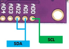
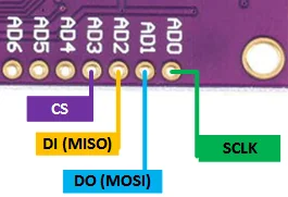
| FT232H | 12 pins. AD4–AD7 are GPIO 0–3, AC0–AC7 are GPIO 4–11. | I2C (AD0=SCL, AD1 and AD2=SDA, wired together), SPI (AD0=SCLK, AD1=MOSI, AD2=MISO, AD3=CS) | 3.3V, with 5V-tolerant inputs. |
| MCP2221A | 4 pins. G0–G3 are GPIO 0–3. | I2C (SCL, SDA), UART (RX, TX), 10-bit ADC (G1–G3), 5-bit DAC (G2 or G3, output appears on both) | 3.3V by default; a jumper on the module switches it to 5V. |
| NUMATO USB-GPIO | 8 to 128 pins depending on the model, starting at IO0 as GPIO 0. | Six 10-bit ADC channels (IO0–IO3 and IO6–IO7 on the 8-channel model) | 5V |
FT232H
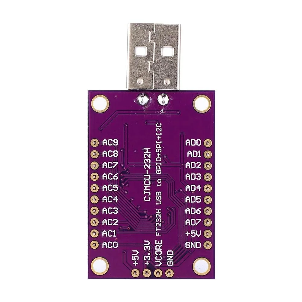
A high-speed USB bridge IC from FTDI that provides GPIO, UART, SPI, I2C, JTAG, and other functions over USB 2.0 Hi-Speed (480Mb/s). Its logic level is 3.3V, but its I/O pins are 5V tolerant, so 5V inputs can be connected to its GPIO. The +5V, +3.3V, and GND pins supply power to external devices such as LEDs and I2C or SPI devices.
| Pin | Function | GPIO number |
|---|---|---|
| +5V, +3.3V | Power | - |
| GND | GND | - |
| AD0 | I2C SCL, SPI SCLK | - |
| AD1 | I2C SDA, SPI MOSI | - |
| AD2 | I2C SDA, SPI MISO | - |
| AD3 | SPI CS | - |
| AD4, AD5, AD6, AD7 | GPIOL0 to GPIOL3 | 0, 1, 2, 3 |
| AC0 to AC7 | GPIOH0 to GPIOH7 | 4 to 11 (AC0 is 4, AC7 is 11) |
MCP2221A
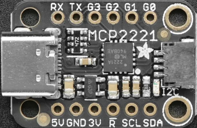
A USB conversion module built on the MCP2221A chip, providing GPIO, I2C, ADC, DAC, and UART. The description below is based on the Adafruit MCP2221A board; pin layout and jumper positions can differ between modules.
| Pin | Function | GPIO number |
|---|---|---|
| 5V | 5V power supplied from USB | - |
| 3.3V (3V) | 3.3V power from the internal voltage regulator | - |
| GND | Common ground for power and logic | - |
| RST (R) | Reset. Driving it LOW resets the module. | - |
| SCL, SDA | I2C | - |
| RX, TX | UART receive, transmit | - |
| G0 | GPIO | 0 |
| G1 | GPIO, ADC1 | 1 |
| G2 | GPIO, ADC2, DAC | 2 |
| G3 | GPIO, ADC3, DAC | 3 |
The ADC is 10-bit (0 to 1023) and the DAC 5-bit (0 to 31); the DAC output appears on G2 and G3 at the same time. Digital I/O, ADC, DAC, I2C, and UART default to a 3.3V level, and the ADC input and DAC output ranges follow that level as 0 to 3.3V or 0 to 5V. To switch to the 5V level, cut the 3V jumper trace on the back of the module and solder the 5V jumper.
The UART appears as a USB serial device: /dev/ttyACM0 or similar on Linux, and a
COM port on Windows.
NUMATO USB-GPIO
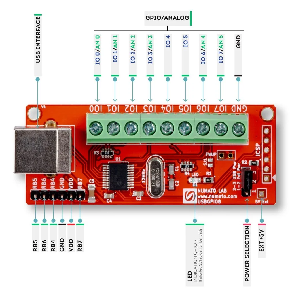
A USB module providing GPIO and ADC, available in models from 8 to 128 channels. The following describes the 8-channel model. Digital I/O runs at a 5V level, and the ADC is 10-bit (0 to 1023) with a 0 to 5V input range. The VDD pin supplies 5V to connected devices.
| Pin | Function | GPIO number |
|---|---|---|
| IO0 to IO3 | GPIO, ADC0 to ADC3 | 0 to 3 |
| IO4, IO5 | GPIO | 4, 5 |
| IO6, IO7 | GPIO, ADC4, ADC5 | 6, 7 |
| VDD | 5V power | - |
| GND | GND | - |
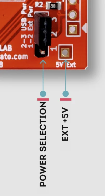
If the connected devices draw more current than the USB port allows, move the power selection jumper to 1-2 (Ext Pwr) and supply external power through the 5V Ext pin.
Finding an I2C Address
Registering an I/O device requires its I2C address. Running the command below in the controller's terminal lists the addresses of devices on the hardware I2C pins in hexadecimal. The bus number can differ by board.
sudo i2cdetect -y 1
The command reports addresses only, not device names or types. With several devices attached, check each device's datasheet to match addresses to devices. Devices wired to pins other than the hardware I2C pins (software I2C) cannot be found this way.
Changing the 1-Wire Pin
The Raspberry Pi's 1-Wire pin defaults to GPIO 4. To wire a device such as the DS18B20 to another pin, edit the configuration file.
sudo nano /boot/firmware/config.txt
Find dtoverlay=w1-gpio and name the pin to use. For several 1-Wire pins,
write several lines. Save the file and reboot with sudo reboot to apply.
dtoverlay=w1-gpio,gpiopin=17
dtoverlay=w1-gpio,gpiopin=27
/boot/firmware/config.txt; on earlier versions it is
/boot/config.txt.
Serial (UART) Ports
Modbus and User Defined Communication need a port name. The Raspberry Pi's UARTs appear as the following devices.
| UART | Device name | Description |
|---|---|---|
| Primary | /dev/serial0 | The port on the hardware UART pins (GPIO 14 and 15). Its actual type varies by model, so this name is the safe one to use. |
| Secondary | /dev/serial1 | Reserved for Bluetooth on models that have it. |
| Full UART | /dev/ttyAMA0 | The full-featured UART. |
| Mini UART | /dev/ttyS0 | Lower performance, with some features missing. |
| USB-TTL converter | /dev/ttyUSB* | FT232RL, CP2102, PL2303, and CH340 chipsets are supported. After connecting, check with ls -l /dev/ttyUSB*. |
The Raspberry Pi has two kinds of UART: the full UART (PL011) and the mini UART. The mini UART has lower performance and lacks some features (parity bit, framing error detection, and others), and its clock is tied to the VPU core clock, so its baud rate changes when the core frequency changes. Which kind serves as the primary UART on the hardware UART pins (GPIO 14 and 15) depends on the model.
| Model | Primary UART | Secondary UART |
|---|---|---|
| Raspberry Pi Zero, 1, 2 | Full UART (UART0) | Mini UART (UART1) |
| Raspberry Pi Zero W, Zero 2 W | Mini UART (UART1) | Full UART (UART0), reserved for Bluetooth |
| Raspberry Pi 3, 4 | Mini UART (UART1) | Full UART (UART0), reserved for Bluetooth |
| Raspberry Pi 5 | UART10 (the board's 3-pin debug header) | Dedicated Bluetooth UART |
Since Raspberry Pi OS Bookworm the configuration file is at
/boot/firmware/config.txt. Every procedure below takes effect after editing
this file and rebooting.
sudo nano /boot/firmware/config.txt
In the nano editor, save with Ctrl + O and Enter, and exit with Ctrl + X. Reboot with
sudo reboot.
Using the Full UART Instead of the Mini UART (Raspberry Pi 3, 4, Zero W, Zero 2 W)
On models whose primary UART is the mini UART, serial communication can be unreliable as the core frequency changes. When stable communication is needed, as with Modbus RTU, make the full UART (UART0) the primary UART. There are two ways; add one of them to the end of the configuration file and reboot.
- Disable Bluetooth and make the full UART primary: Disable the Bluetooth modem service (
sudo systemctl disable hciuart) and adddtoverlay=disable-btto the configuration file. Bluetooth is no longer available afterwards. - Move Bluetooth to the mini UART and make the full UART primary: Add
core_freq=250, which fixes the core clock, anddtoverlay=miniuart-btto the configuration file. Bluetooth remains available, but its maximum baud rate may be lower.
# To disable Bluetooth
dtoverlay=disable-bt

# To move Bluetooth to the mini UART
core_freq=250
dtoverlay=miniuart-bt
After rebooting, /dev/serial0 points to the full UART
(/dev/ttyAMA0).
Using the Hidden UARTs (Raspberry Pi 4)
The Raspberry Pi 4 has four hidden full UARTs (UART2 to UART5). Add the lines you need to
the end of the configuration file and reboot; they appear as ttyAMA1 onward,
which dmesg | grep tty confirms.
dtoverlay=uart2
dtoverlay=uart3
dtoverlay=uart4
dtoverlay=uart5
| UART | TXD | RXD |
|---|---|---|
| UART2 | GPIO 0 | GPIO 1 |
| UART3 | GPIO 4 | GPIO 5 |
| UART4 | GPIO 8 | GPIO 9 |
| UART5 | GPIO 12 | GPIO 13 |
The GPIO numbers of the TX and RX pins can also be set directly.
dtoverlay=uart2,txd2_pin=16,rxd2_pin=17
uart0-pi5 through uart4-pi5. The pins and options each
one uses can be listed with, for example, dtoverlay -h uart2-pi5.
With a USB-TTL converter connected, ls -l /dev/ttyUSB* lists the ports of the
attached converters (ttyUSB0, ttyUSB1, and so on); use that name
as the port name.