I/O Device
Settings → I/O Device registers the sensors, motors, displays, and other devices used by the I/O Device Control action. See Part 7 for the list of supported devices and how their commands are organized. The fields in the registration dialog depend on the type of the selected device.
- Enter a Name. Any name can be used.
- Under GPIO, choose where the device is wired: the controller board's onboard GPIO or a USB-GPIO adapter. Choosing USB-GPIO shows a USB GPIO field for picking an adapter registered under External GPIO.
- Click the I/O Device field to open the device list, then search for the device and select it. The list appears only after GPIO has been chosen. Once a device is selected, Description and Type are filled in automatically.
- Enter the connection fields for the type, as listed in the table below.
- Check the values under Initialization Commands and save.
| Type | Field | Description |
|---|---|---|
| I2C | Interface | Shown for onboard GPIO only. Choose Hardware or Software. |
| I2C Bus, SDA Pin, SCL Pin | The hardware interface takes the I2C Bus number; the software interface takes the GPIO numbers of the SDA Pin and SCL Pin. | |
| I2C Address | Pick from the list or type it in; typed values use hexadecimal form such as 0xFF. See the Appendix for how to find the address of a connected device. | |
| SPI | Interface | Shown for onboard GPIO only. Choose Hardware or Software. |
| SPI Bus, Chip Select (CS), four pins | The hardware interface takes the SPI Bus number and the Chip Select (CS) number; the software interface takes the GPIO numbers of the CS Pin, SCLK Pin, MISO Pin, and MOSI Pin. | |
| UART | Port | The serial port the device is connected to; find it with the search button or type it in (e.g. COM3 on Windows, /dev/ttyACM0 on Linux). |
| ONE_WIRE | 1-Wire ID | Click Scan to list every connected 1-Wire device, then pick one from the list. |
With a USB-GPIO adapter selected, the interface, bus, and pin fields are not shown; only the I2C address, port, or 1-Wire ID is entered, depending on the type.
Interface
- Hardware: Uses the board's hardware I2C or SPI interface. Fast and stable, but limited to the dedicated GPIO pins.
- Software: Implements the I2C or SPI protocol in software (bit-banging). CPU load rises and it is slower, but any GPIO pin can be used.
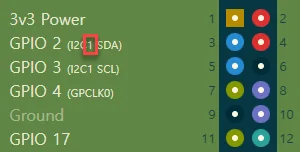
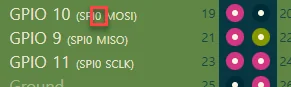
The hardware I2C and SPI bus numbers are printed on each board's pin map. On a Raspberry Pi the I2C bus is 1 (GPIO 2 SDA, GPIO 3 SCL) and the SPI bus is 0 (GPIO 10 MOSI, GPIO 9 MISO, GPIO 11 SCLK).
Initialization Commands
Initialization commands are the device commands needed to start the device, and each takes its own values. When RUN is clicked on the controller, the initialization commands of every registered I/O device run automatically and initialize the device.